Home

Intuición entrada Mil millones and logic gate circuit diagram activación estar su

Digital Electronics and Logic Circuits (Role of Transistors)

The logic gate equivalent to the given circuit diagram is: - Sarthaks  eConnect | Largest Online Education Community
The logic gate equivalent to the given circuit diagram is: - Sarthaks eConnect | Largest Online Education Community

Logic gate - Wikipedia

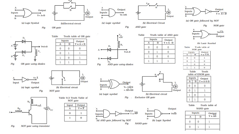
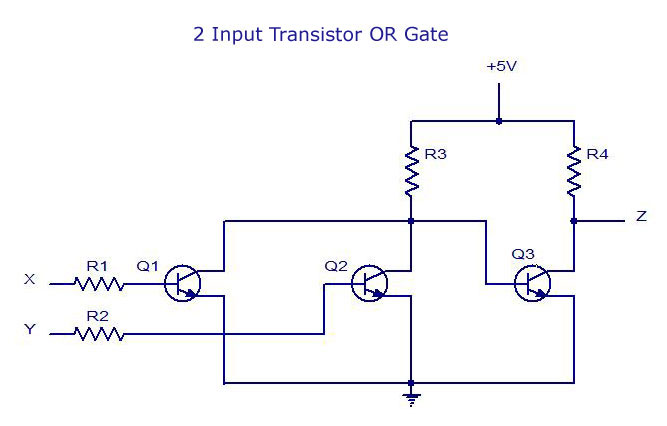
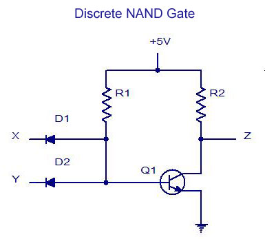
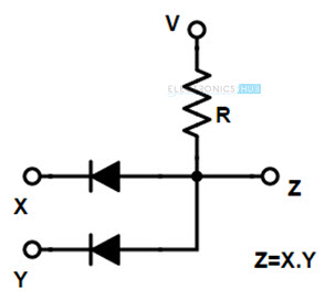
Basic logic gates using discrete components

Basic Logic Gates
Basic Logic Gates

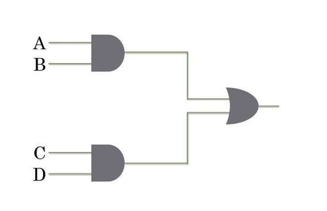
The diagram of the logic gate circuit is given below. The output Y of the  circuit is represented by\n \n \n \n \n (A) \\[A \\cdot \\left( {B + C}  \\right)\\](B) \\[A \\
The diagram of the logic gate circuit is given below. The output Y of the circuit is represented by\n \n \n \n \n (A) \\[A \\cdot \\left( {B + C} \\right)\\](B) \\[A \\
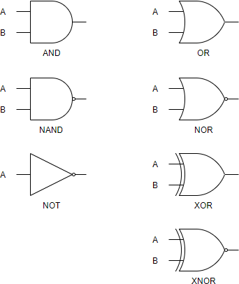
Digital Electronics-Logic Gates Basics,Tutorial,Circuit Symbols,Truth Tables

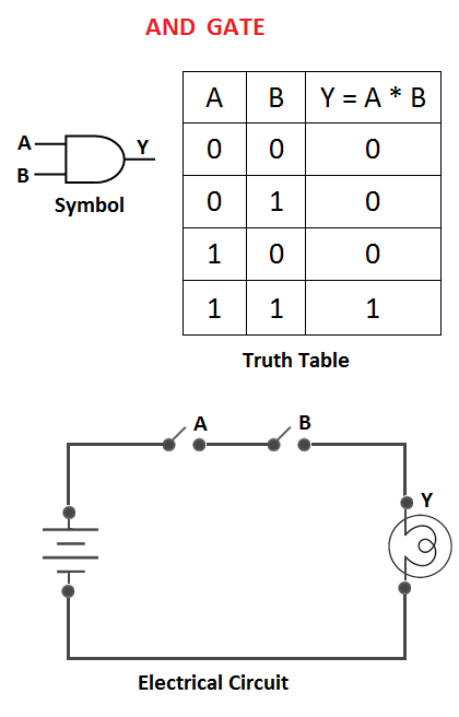
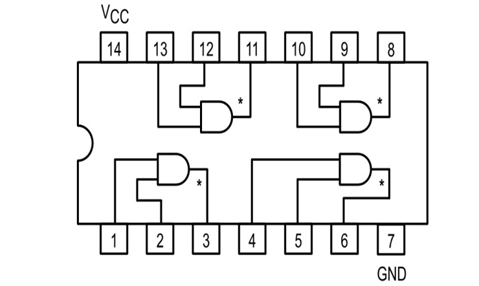
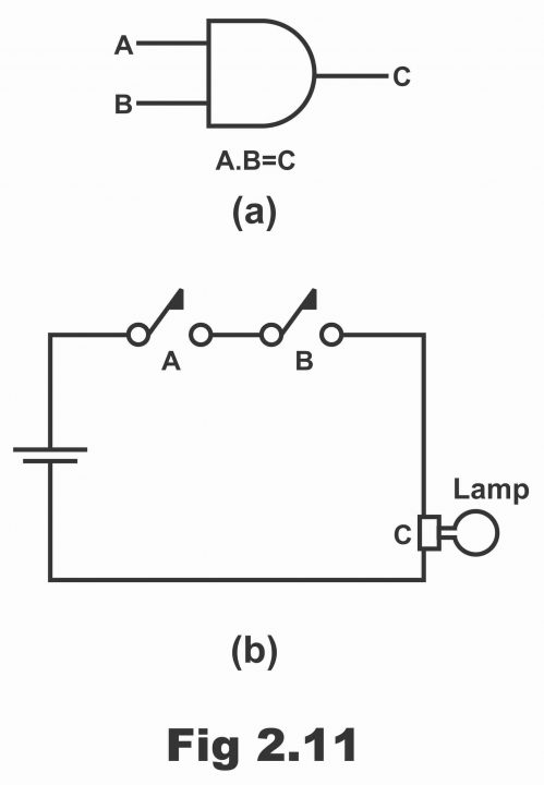
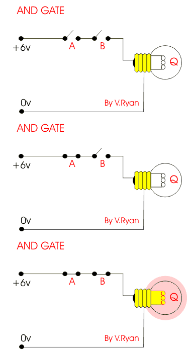
AND Gate: What is it? (Working Principle & Circuit Diagram) | Electrical4U

The schematic layout of logic gate training kit. | Download Scientific  Diagram
The schematic layout of logic gate training kit. | Download Scientific Diagram

Digital Electronics-Logic Gates Basics,Tutorial,Circuit Symbols,Truth Tables

Make a chart of circuit diagram of all logic gate

Logic Gates Circuit Diagram & Working - Your Electrical Guide

Digital Logic AND Gate - ElectronicsHub

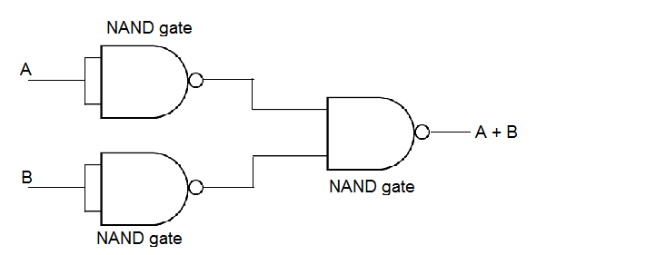
Draw a diagram of show how NAND gates can be combined to obtain an OR gate.(Truth  table is not required).
Draw a diagram of show how NAND gates can be combined to obtain an OR gate.(Truth table is not required).

a) What are logic gates?(b) Draw a circuit diagram for dual - input AND Gate  by using two diodes.
a) What are logic gates?(b) Draw a circuit diagram for dual - input AND Gate by using two diodes.

Implementing Any Circuit Using NAND Gate Only - GeeksforGeeks

Logic Gates, AND Gate, OR Gate, NOR Gate, NAND Gate, Truth Table

Logic Gates software | Draw Logic Gates Online | Creately

Basic Logic Gates using NAND Gate | NOT, OR, AND Gates

Universal Gates-NAND Gate - ElectronicsHub

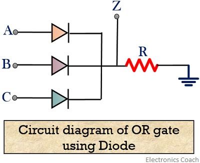
What are Logic gates? OR, AND, NOT logic gate with truth table -  Electronics Coach
What are Logic gates? OR, AND, NOT logic gate with truth table - Electronics Coach

What is Logic Diagram and Truth Table?

Logic AND Gate Tutorial with Logic AND Gate Truth Table

Logic Gates Diagrams - 101 Computing

Basic Logic Gates
Basic Logic Gates

Design of Basic Logic Gates using NAND Gate | Nand gate, Circuit board  design, Logic design
Design of Basic Logic Gates using NAND Gate | Nand gate, Circuit board design, Logic design

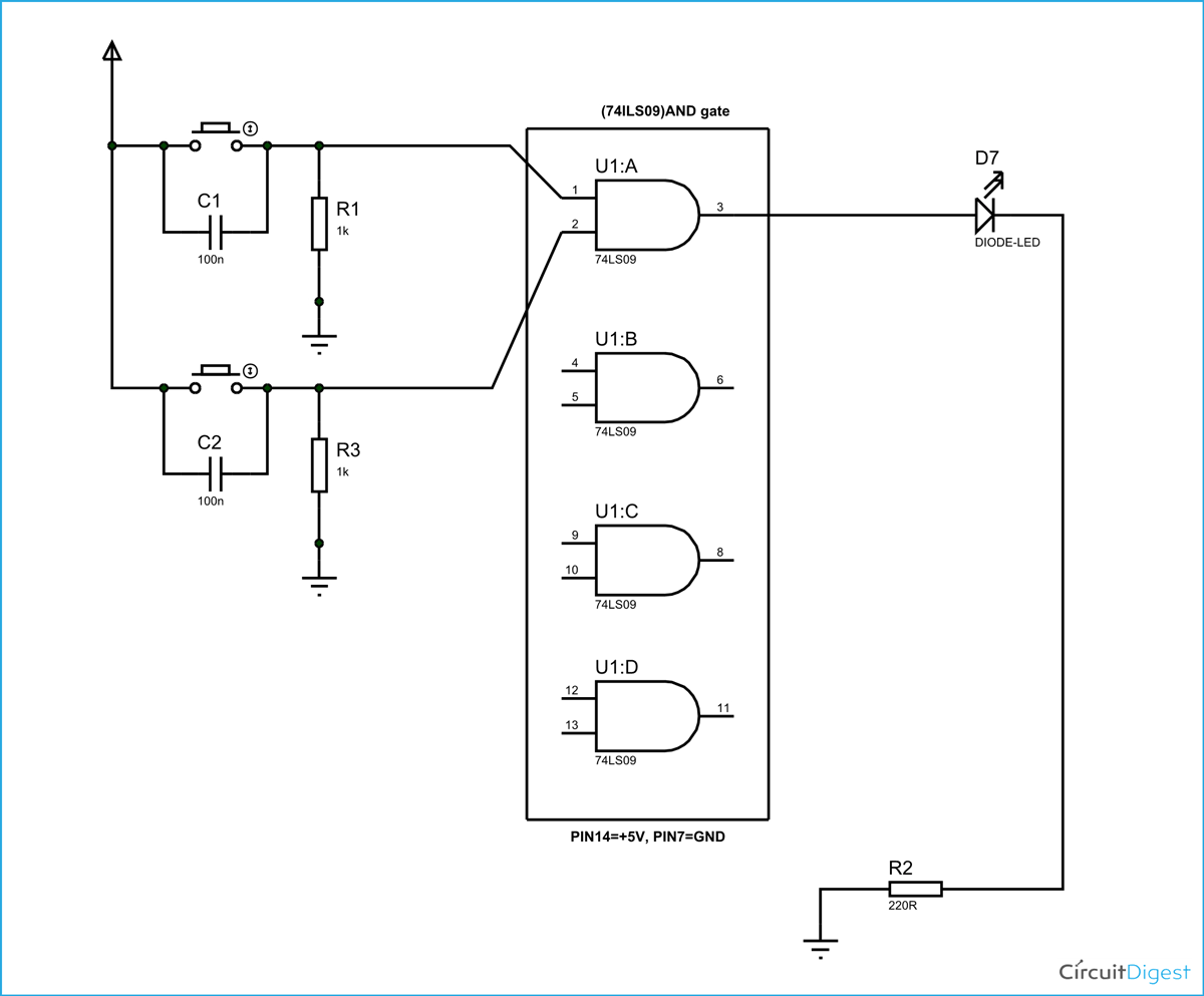
AND Gate Circuit Diagram & Working Explanation

AND Gate Circuit Diagram & Working Explanation

Logic AND Gate Working Principle & Circuit Diagram